How it works
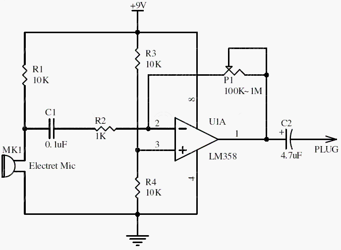
An electret microphone produces a small AC signal superimposed on its bias voltage. R1 supplies the microphone bias, while the input capacitor passes the audio into the amplifier and blocks the DC component. The resistor network around the LM358 establishes the operating point and gain.
P1 changes the amplification. Begin at low gain and increase it until speech is clear without clipping. More gain also amplifies background noise, so the highest setting is not necessarily the best setting.
Original schematic
CLICK TO ENLARGEOn the bench
Use short, screened microphone leads and a clean supply. For an ADC connection, check the output voltage range and DC offset against the ADC limits; AC coupling alone does not provide input protection.
Resources & provenance
Rewritten from the original circuits/aum/lj3on1t_aum002.php page. Component values and historical performance claims have not been independently bench-tested. The circuit figures have had their watermarks removed.
Browse all surviving downloads →