How it works
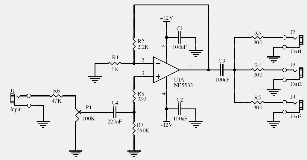
An audio source enters at J1 and passes through P1, which sets the input level. U1 buffers and amplifies the signal so it can be distributed to the three output lines without loading the source as heavily as a direct split would.
These are signal outputs, not loudspeaker outputs. The archive describes operation with 300 Ω lines, but the usable level and loading should be checked against the actual amplifier and supply arrangement.
Original schematic
CLICK TO ENLARGEOn the bench
Test one output first, then connect the remaining loads while monitoring amplitude and distortion. A common signal ground is needed unless an additional isolation stage is provided.
Resources & provenance
Rewritten from the original circuits/aum/lj3on1t_aum005.php page. Component values and historical performance claims have not been independently bench-tested. The circuit figures have had their watermarks removed.
Browse all surviving downloads →