How it works
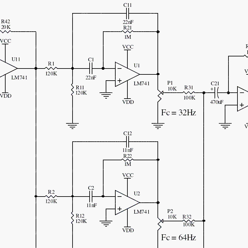
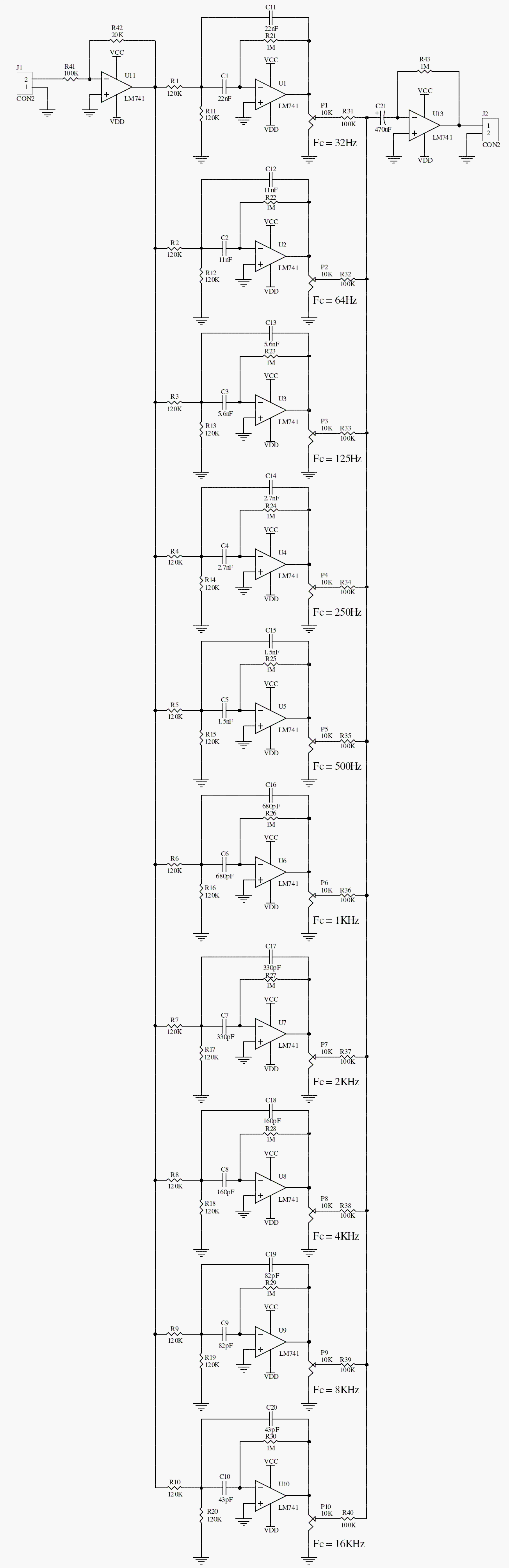
The equalizer divides the audio spectrum into ten overlapping bands. Each active filter changes the contribution of its band, and the output circuitry recombines the signals. The input stage establishes a suitable level; the final amplifier drives the following line-level equipment.
The archive specifies split supplies between ±12 V and ±15 V. This means positive and negative rails relative to a common 0 V reference, not a single supply of 12–15 V.
Original schematic
CLICK TO ENLARGEOn the bench
Verify all supply polarities before inserting the op-amps. Begin with the controls centered, then test each band individually; multiple boosted bands can cause clipping even with a modest input signal.
Resources & provenance
Rewritten from the original circuits/aum/lj3on1t_aum008.php page. Component values and historical performance claims have not been independently bench-tested. The circuit figures have had their watermarks removed.
Browse all surviving downloads →