How it works
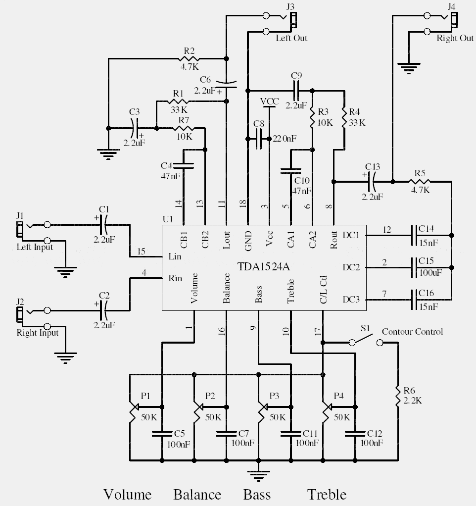
This circuit combines several audio controls around one dedicated IC. P1 sets volume, P2 sets balance, and P3 and P4 adjust bass and treble. S1 selects the contour function. J1 and J2 are the inputs, with the corresponding outputs on J3 and J4.
The original notes specify a single 9–15 V supply. Check the IC and schematic for the acceptable input level; microphone and line sources are not interchangeable without considering gain and impedance.
Original schematic
CLICK TO ENLARGEOn the bench
Use a low-level test signal first. If the source overdrives the input, add a suitable attenuator rather than relying on the output volume control to remove distortion.
Resources & provenance
Rewritten from the original circuits/aum/lj3on1t_aum009.php page. Component values and historical performance claims have not been independently bench-tested. The circuit figures have had their watermarks removed.
Browse all surviving downloads →