How it works
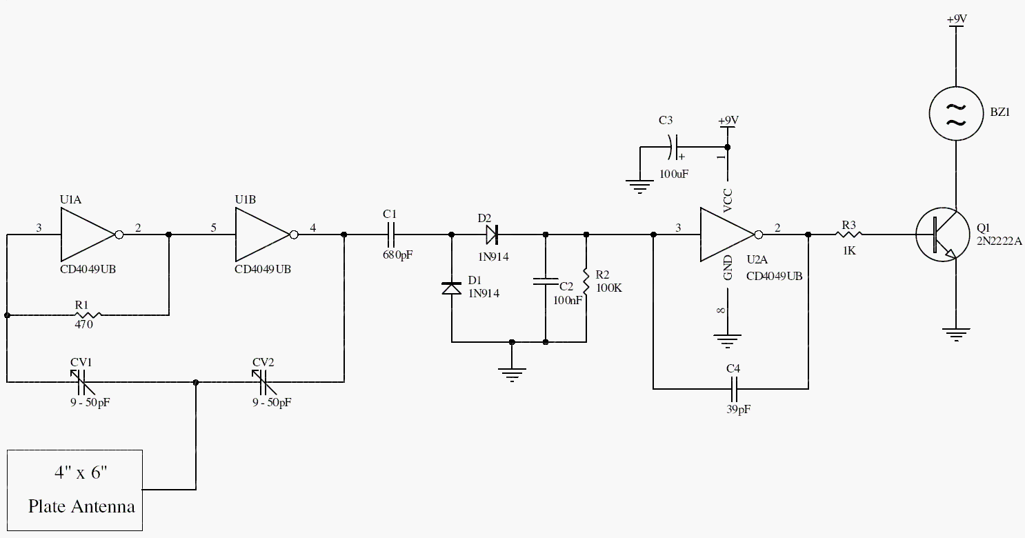
U1a and U1b form an oscillator whose behavior depends partly on the pickup plate’s capacitance. A detector network converts oscillation into a DC control level. When the oscillation changes enough, U1c and Q1 activate the buzzer.
C1 and C2 set the operating point close to the oscillation threshold. The original 3–5 inch sensitivity is an approximate observation; plate geometry, grounding, humidity, and nearby wiring change the result.
Original schematic
CLICK TO ENLARGEOn the bench
Use a nonconductive adjustment tool. First establish steady oscillation, then approach the threshold gradually and test repeatability with the plate installed in its intended position.
Resources & provenance
Rewritten from the original circuits/sec/mn3qo9c_sec001.php page. Component values and historical performance claims have not been independently bench-tested. The circuit figures have had their watermarks removed.
Browse all surviving downloads →