How it works
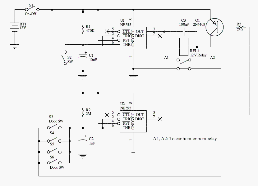
Closing S1 powers the circuit. Opening the normally closed S2 starts an exit interval set by R1 and C1. A later door opening longer than the second timing interval causes the horn output to activate.
The archive quotes approximately five seconds to exit and a two-second door interval. Resistor and capacitor tolerances affect both; measure the actual timing on the assembled circuit.
Original schematic
CLICK TO ENLARGEOn the bench
Verify the reset and disarm behavior with an indicator before connecting a horn. Vehicle loads need suitable drive, fusing, and transient protection beyond a successful bench demonstration.
Resources & provenance
Rewritten from the original circuits/sec/mn3qo9c_sec004.php page. Component values and historical performance claims have not been independently bench-tested. The circuit figures have had their watermarks removed.
Browse all surviving downloads →