How it works
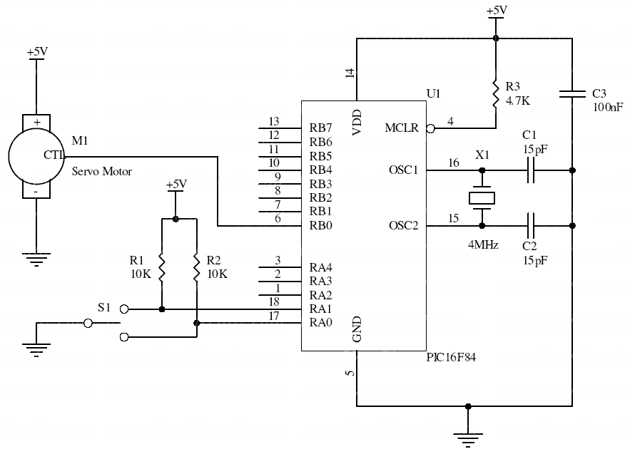
The PIC repeatedly sends a control pulse to a hobby servo. The switch changes the requested pulse width, while the loop repeats the pulse at roughly a 20 ms interval. The original PICBasic code changes the command incrementally while a direction is selected.
Typical starting values are around 1 ms, 1.5 ms, and 2 ms, but the corresponding angles and safe travel depend on the servo. They should not be described as universal −45°, 0°, and +45° positions.
Original schematic
CLICK TO ENLARGEOn the bench
Use a supply capable of the servo’s starting and stall current and connect its ground to the controller ground. Start near the center pulse width and expand travel carefully without forcing the mechanism.
Original PICBasic example
Historical source. Pulse timing depends on the compiler and clock configuration; verify before connecting a servo.
Symbol porta = 5
                b3 = 150
                start:
                Peek porta,b0
                If bit0 = 0 Then sweepl
                If bit1 = 0 Then sweepr
                Pulsout 0,b3
                Pause 18
                Goto start
                sweepl:
                b3 = b3 + 1
                Pulsout 0,b3
                Pause 18
                If b3 > 200 Then hold1
                Goto start
                sweepr:
                b3 = b3 - 1
                Pulsout 0,b3
                Pause 18
                If b3 < 100 Then hold2
                Goto start
                hold1:
                b3 = 200
                Goto start
                hold2:
                b3 = 100
                Goto start
Resources & provenance
Rewritten from the original circuits/uct/di29o1l_uct001.php page. Component values and historical performance claims have not been independently bench-tested. The circuit figures have had their watermarks removed.
Browse all surviving downloads →