How it works
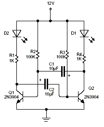
Cross-coupled transistor stages switch one another on and off through timing capacitors. Each transition changes which LED receives current, creating the alternating pattern. The timing resistors and capacitors determine the approximate period.
The original 12 V design uses 1 kΩ LED resistors for blue or white LEDs and suggests 2.2 kΩ for lower-forward-voltage red, green, or yellow LEDs. Calculate current for the actual LED rather than choosing a resistor by color alone.
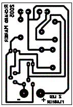
Original archive figures
CLICK TO ENLARGEOn the bench
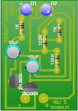
Estimate LED current from (supply voltage − LED forward voltage − transistor drop) / resistance. Check resistor dissipation, capacitor polarity, and the actual period on the bench.
Resources & provenance
Rewritten from the original projects/sub/d3mn6sf_prjsub001.php page. Component values and historical performance claims have not been independently bench-tested.
Browse all surviving downloads →