How it works
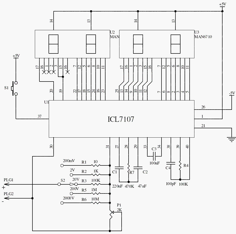
The ICL7107 combines an analog-to-digital converter, reference functions, and LED display drive. The input divider and range switch scale the measured voltage into the converter’s supported differential input range.
Calibrate the reading against a known low-voltage source using P1. A good PCB layout, a stable reference, and separation between sensitive analog wiring and display currents are important for repeatable readings.
Original schematic
CLICK TO ENLARGEOn the bench
Use only low-voltage bench signals until the complete input protection is reviewed. A range switch alone does not make a homemade meter safe for mains measurements.
Resources & provenance
Rewritten from the original circuits/msr/r3j19ns_msr001.php page. Component values and historical performance claims have not been independently bench-tested. The circuit figures have had their watermarks removed.
Browse all surviving downloads →