How it works
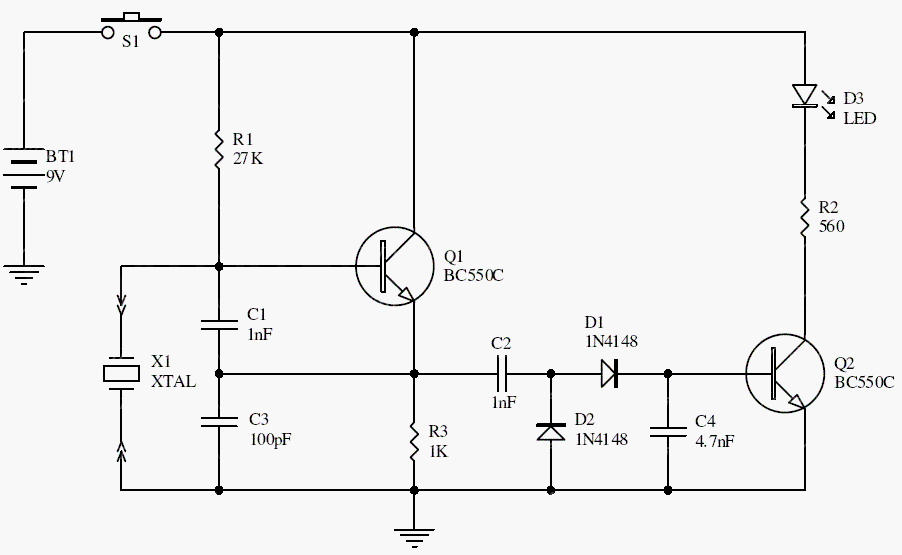
T1 and the crystal form an oscillator with C1 and C2 providing feedback. The detector network rectifies the oscillator signal, and T2 drives an LED to indicate detected activity.
The archive describes a nominal 100 kHz–30 MHz test range. Whether a particular crystal starts also depends on its mode, load capacitance, drive requirements, and the fixture’s stray capacitance.
Original schematic
CLICK TO ENLARGEOn the bench
An illuminated LED indicates oscillation, not frequency accuracy. A dark LED does not conclusively prove a faulty crystal; confirm the supply, socket connections, and oscillator suitability first.
Resources & provenance
Rewritten from the original circuits/msr/r3j19ns_msr004.php page. Component values and historical performance claims have not been independently bench-tested. The circuit figures have had their watermarks removed.
Browse all surviving downloads →