How it works
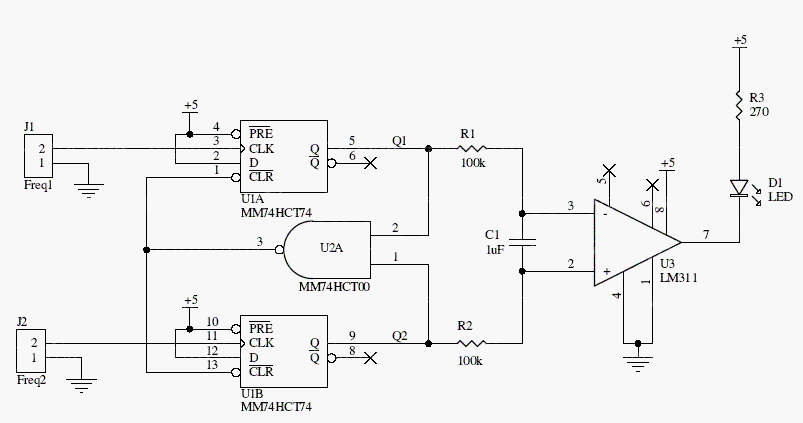
Each input drives a D-type flip-flop. Their outputs and a NAND reset network produce pulses related to the relative timing of the two inputs. A low-pass network converts the differing pulse activity into voltages for the LM311 comparator.
The result indicates which input is faster rather than displaying either frequency numerically. Behavior near equal frequencies depends on input phase, filtering, and comparator behavior.
Original schematic
CLICK TO ENLARGEOn the bench
Use clean logic-level inputs compatible with the 74HCT devices and avoid floating inputs. Source attribution in the archive: Electronics Design magazine, September 5, 1995.
Resources & provenance
Rewritten from the original circuits/msr/r3j19ns_msr006.php page. Component values and historical performance claims have not been independently bench-tested. The circuit figures have had their watermarks removed.
Browse all surviving downloads →