How it works
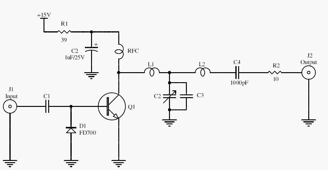
A class-C stage conducts for less than half of each RF cycle. Its tuned output network selects the desired fundamental and transforms impedances between the transistor and load. This can be efficient for appropriate constant-envelope signals.
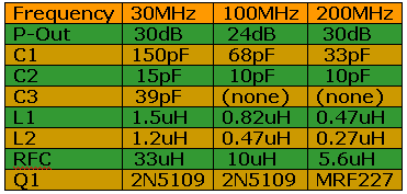
The archive describes approximately 1 W output and frequency-dependent component choices. Its power table assumes 13 dBm input drive; performance outside those conditions must be evaluated separately.
Original schematic
CLICK TO ENLARGEOn the bench
Test into a correctly rated dummy load with suitable filtering and measurement equipment. Check device dissipation, load match, and harmonic output before considering an antenna connection.
Resources & provenance
Rewritten from the original circuits/rfr/hg65q0p_rfr001.php page. Component values and historical performance claims have not been independently bench-tested. The circuit figures have had their watermarks removed.
Browse all surviving downloads →