How it works
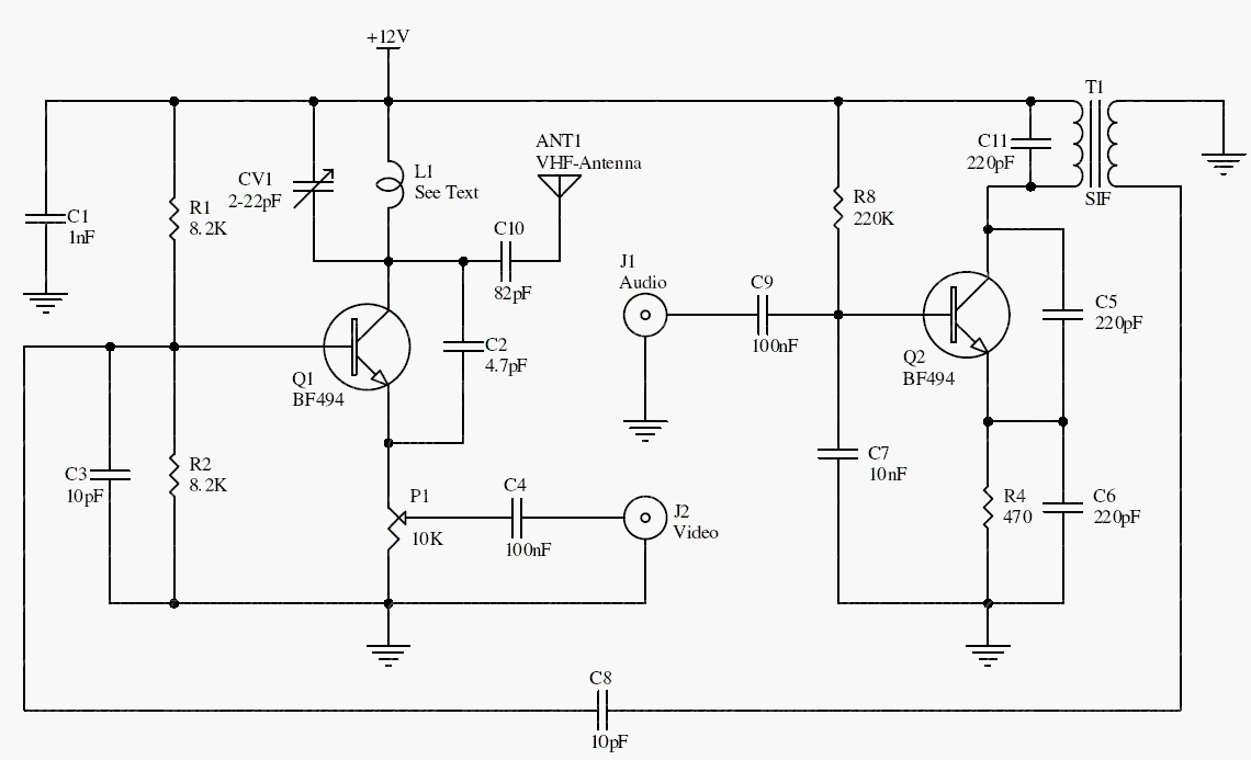
Q1 forms the main RF oscillator and mixer. A separate Q2 oscillator carries frequency-modulated audio at a nominal 5.5 MHz offset, while the composite video drives the video modulation path.
The archived example targets analog system-B channel 5, with a 175.25 MHz picture carrier and a 180.75 MHz sound carrier. It requires compatible analog receiving equipment; it does not generate a digital TV signal.
Original schematic
CLICK TO ENLARGEOn the bench
Use a wired, attenuated bench connection to suitable test equipment. Treat the quoted short range as an anecdotal observation, and check oscillator frequency and unwanted emissions independently.
Resources & provenance
Rewritten from the original circuits/rfr/hg65q0p_rfr003.php page. Component values and historical performance claims have not been independently bench-tested. The circuit figures have had their watermarks removed.
Browse all surviving downloads →