How it works
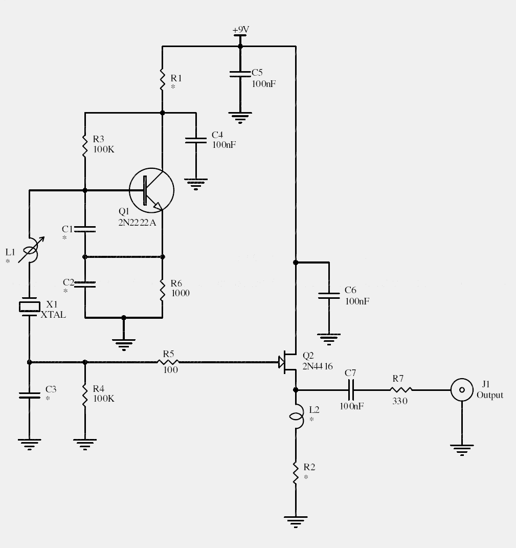
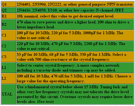
The crystal establishes the operating frequency, while the surrounding network controls feedback and drive. A JFET buffer reduces the effect of the following load on the oscillator. L1 provides fine frequency adjustment.
Changing C3 changes loading and drive as well as amplitude. Fundamental and overtone crystals require different operating conditions; the original under-1 mW design intention is not a substitute for the crystal manufacturer’s limit.
Original schematic
CLICK TO ENLARGEOn the bench
Measure crystal drive where possible and avoid excessive loading. A 50 Ω output requires an appropriate additional buffer or matching network rather than a direct connection to a sensitive oscillator node.
Resources & provenance
Rewritten from the original circuits/rfr/hg65q0p_rfr004.php page. Component values and historical performance claims have not been independently bench-tested. The circuit figures have had their watermarks removed.
Browse all surviving downloads →