How it works
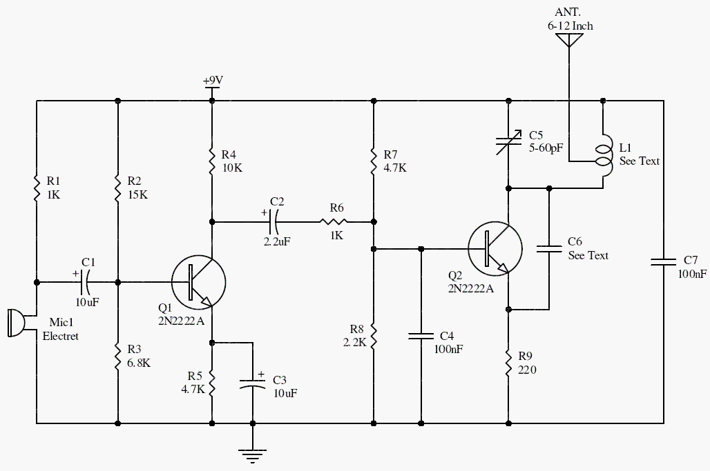
Q1 amplifies the microphone signal. Q2 and its tuned network form an oscillator whose frequency changes with the audio signal. Coil geometry, wiring capacitance, and nearby objects can all shift the oscillator frequency.
The original claim that a battery size and short antenna automatically establish regulatory compliance has been removed. Neither defines radiated field strength, occupied bandwidth, or unwanted emissions.
Original schematic
CLICK TO ENLARGEOn the bench
Keep this as a controlled RF experiment using a suitable load or shielded setup. Confirm the relevant transmission requirements before radiating; a receiver alone cannot verify compliance or spectral purity.
Resources & provenance
Rewritten from the original circuits/rfr/hg65q0p_rfr002.php page. Component values and historical performance claims have not been independently bench-tested. The circuit figures have had their watermarks removed.
Browse all surviving downloads →