How it works
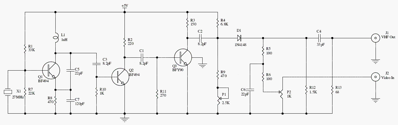
The crystal oscillator and harmonic selection establish an RF carrier. Composite video enters at J2 and modulates that carrier; the RF output is taken from J1. P1 and P2 adjust the video operating conditions.
The archive describes output around 189 MHz. This circuit carries video only: it does not add an audio subcarrier or encode a digital broadcast signal.
Original schematic
CLICK TO ENLARGEOn the bench
Use compatible analog test equipment and a wired, attenuated connection. Check levels and waveform quality at each stage before adjusting the RF output.
Resources & provenance
Rewritten from the original circuits/rfr/hg65q0p_rfr005.php page. Component values and historical performance claims have not been independently bench-tested. The circuit figures have had their watermarks removed.
Browse all surviving downloads →