How it works
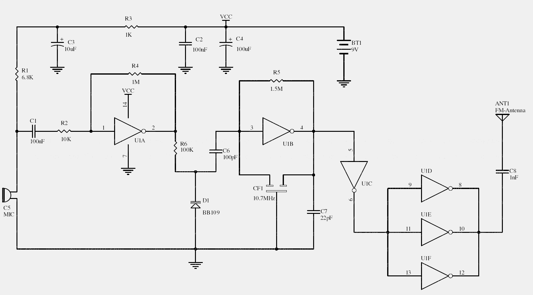
N2 forms the RF oscillator, N3 buffers it, and parallel inverter stages provide additional drive. Audio amplified by N1 changes a varactor’s capacitance, shifting the oscillator frequency.
The original design deliberately uses the ninth harmonic of 10.7 MHz, near 96.3 MHz. A square-wave source also generates many unwanted harmonics, so it is not a spectrally clean transmitter by itself.
Original schematic
CLICK TO ENLARGEOn the bench
Use a shielded bench setup and suitable attenuation. Proper filtering and output characterization are essential; paralleling logic outputs also requires checking the exact device’s suitability.
Resources & provenance
Rewritten from the original circuits/rfr/hg65q0p_rfr006.php page. Component values and historical performance claims have not been independently bench-tested. The circuit figures have had their watermarks removed.
Browse all surviving downloads →