How it works
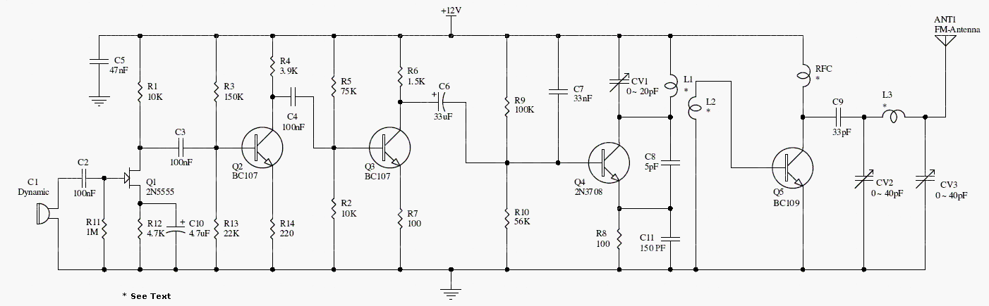
The audio stage begins with a high-impedance FET input followed by transistor amplification. A 2N3708 stage generates and modulates the carrier, and a coupled RF output stage increases its power.
The archived coil details are L1: 6 turns of 1 mm wire on a 7 mm air core; L2: 3 turns alongside L1; L3: 8 turns of 0.6 mm wire on a 6 mm core; RFC: 25–30 turns of 0.3 mm wire on a 5 mm nonmagnetic former.
Original schematic
CLICK TO ENLARGEOn the bench
Build and test one stage at a time into suitable loads. The quoted 600 mW and 1 km range are unverified; review stability, harmonic filtering, thermal limits, and transmission requirements before any radiated test.
Resources & provenance
Rewritten from the original circuits/rfr/hg65q0p_rfr008.php page. Component values and historical performance claims have not been independently bench-tested. The circuit figures have had their watermarks removed.
Browse all surviving downloads →