How it works
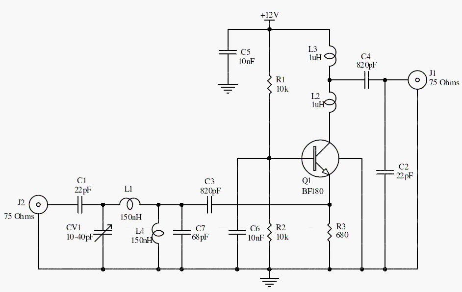
C1, CV1, L1, L4, C7, and C3 form the input filtering network. The BF180 operates in a common-base arrangement, whose relatively low input impedance is useful in RF matching.
The historical gain figure is 15 dB. Coil dimensions, stray capacitance, transistor characteristics, and loading all affect the frequency response and actual gain.
Original schematic
CLICK TO ENLARGEOn the bench
Make the air-core coils and wiring compact and mechanically stable. Align the circuit with an appropriate source and instrument, then check for oscillation in its final shielded enclosure.
Resources & provenance
Rewritten from the original circuits/rfr/hg65q0p_rfr010.php page. Component values and historical performance claims have not been independently bench-tested. The circuit figures have had their watermarks removed.
Browse all surviving downloads →