How it works
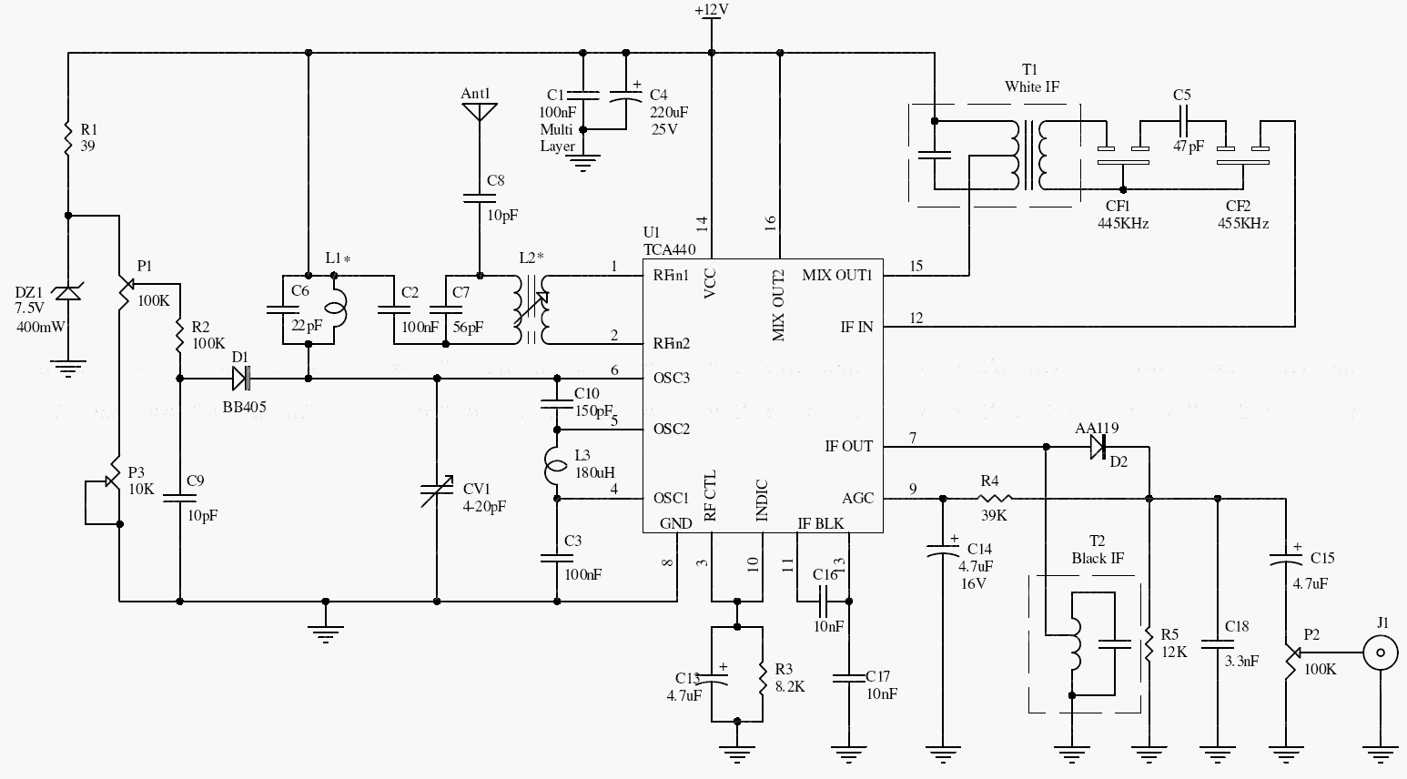
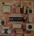
The TCA440 combines RF and intermediate-frequency functions. The antenna signal is coupled through L2, mixed with the local oscillator, filtered at the intermediate frequency, amplified, and finally detected to recover audio.
The archive targets approximately 25–28 MHz. It specifies a 9-turn, 0.3 mm wire L1 on a 4 mm adjustable ferrite former, an L2 with a similar primary and 6-turn secondary, and a 180 µH L3 choke. IF transformer color codes are not a universal specification.
Original schematic
CLICK TO ENLARGEOn the bench
Use a low-level, known AM signal for alignment instead of relying only on background hiss. Confirm the IF filter and transformer characteristics and connect the detected output to a separate audio amplifier.
Resources & provenance
Rewritten from the original circuits/rfr/hg65q0p_rfr011.php page. Component values and historical performance claims have not been independently bench-tested. The circuit figures have had their watermarks removed.
Browse all surviving downloads →