How it works
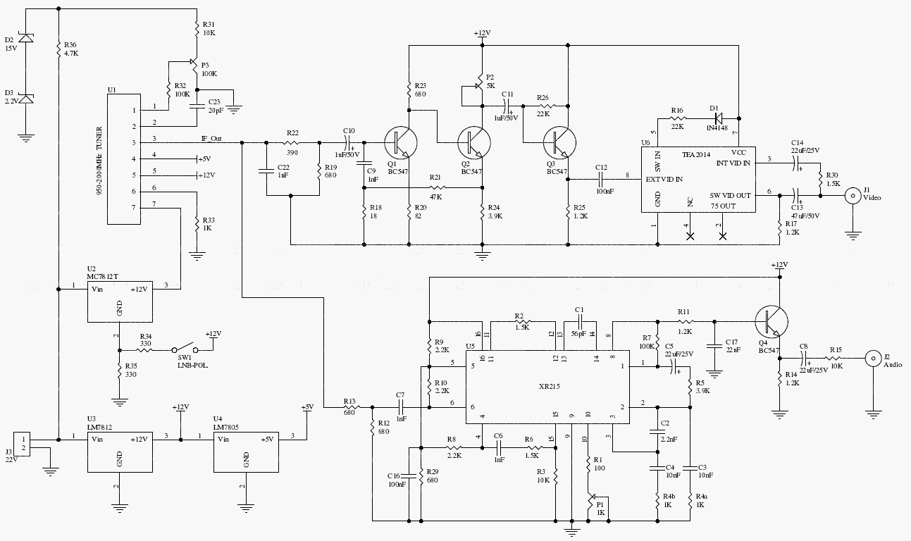
This design uses a 950–2000 MHz tuner with analog video and audio processing. P3 tunes reception, P2 changes the video adjustment, and P1 sets audio level. The original circuit also provides an LNB polarity control.
The archive specifies a 22 V supply and a particular Toshiba tuner. This is an analog-era design and does not decode modern digital satellite formats such as DVB-S or DVB-S2.
Original schematic
CLICK TO ENLARGEOn the bench
Treat the tuner and LNB supply arrangements as device-specific. Check voltage, current, and protection requirements before connecting a dish or LNB; modern reception calls for compatible digital hardware.
Resources & provenance
Rewritten from the original circuits/rfr/hg65q0p_rfr013.php page. Component values and historical performance claims have not been independently bench-tested. The circuit figures have had their watermarks removed.
Browse all surviving downloads →